Chapter 23. Basic Networking
Contents
Linux offers the necessary networking tools and features for integration into all types of network structures. Network access using a network card, modem or other device can be configured with YaST. Manual configuration is also possible. In this chapter only the fundamental mechanisms and the relevant network configuration files are covered.
Linux and other Unix operating systems use the TCP/IP protocol. It is not a single network protocol, but a family of network protocols that offer various services. The protocols listed in Table 23.1, “Several Protocols in the TCP/IP Protocol Family”, are provided for the purpose of exchanging data between two machines via TCP/IP. Networks combined by TCP/IP, comprising a worldwide network, are also referred to as “the Internet.”
RFC stands for Request for Comments. RFCs are documents that describe various Internet protocols and implementation procedures for the operating system and its applications. The RFC documents describe the setup of Internet protocols. To expand your knowledge of any of the protocols, refer to the appropriate RFC documents. These are available at http://www.ietf.org/rfc.html.
Table 23.1. Several Protocols in the TCP/IP Protocol Family
|
Protocol |
Description |
|---|---|
|
Transmission Control Protocol: a connection-oriented secure protocol. The data to transmit is first sent by the application as a stream of data and converted into the appropriate format by the operating system. The data arrives at the respective application on the destination host in the original data stream format it was initially sent. TCP determines whether any data has been lost or jumbled during the transmission. TCP is implemented wherever the data sequence matters. | |
|
User Datagram Protocol: a connectionless, insecure protocol. The data to transmit is sent in the form of packets generated by the application. The order in which the data arrives at the recipient is not guaranteed and data loss is possible. UDP is suitable for record-oriented applications. It features a smaller latency period than TCP. | |
|
Internet Control Message Protocol: Essentially, this is not a protocol for the end user, but a special control protocol that issues error reports and can control the behavior of machines participating in TCP/IP data transfer. In addition, it provides a special echo mode that can be viewed using the program ping. | |
|
Internet Group Management Protocol: This protocol controls machine behavior when implementing IP multicast. |
As shown in Figure 23.1, “Simplified Layer Model for TCP/IP”, data exchange takes place in different layers. The actual network layer is the insecure data transfer via IP (Internet protocol). On top of IP, TCP (transmission control protocol) guarantees, to a certain extent, security of the data transfer. The IP layer is supported by the underlying hardware-dependent protocol, such as ethernet.
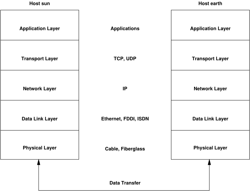
The diagram provides one or two examples for each layer. The layers are ordered according to abstraction levels. The lowest layer is very close to the hardware. The uppermost layer, however, is almost a complete abstraction from the hardware. Every layer has its own special function. The special functions of each layer are mostly implicit in their description. The data link and physical layers represent the physical network used, such as ethernet.
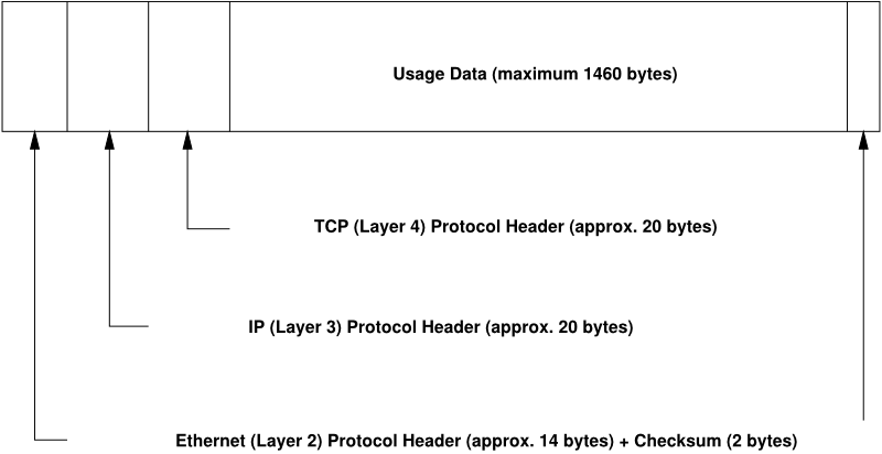
Almost all hardware protocols work on a packet-oriented basis. The data to transmit is collected into packets (it cannot be sent all at once). The maximum size of a TCP/IP packet is approximately 64 KB. Packets are normally quite smaller, as the network hardware can be a limiting factor. The maximum size of a data packet on an ethernet is about fifteen hundred bytes. The size of a TCP/IP packet is limited to this amount when the data is sent over an ethernet. If more data is transferred, more data packets need to be sent by the operating system.
For the layers to serve their designated functions, additional information regarding each layer must be saved in the data packet. This takes place in the header of the packet. Every layer attaches a small block of data, called the protocol header, to the front of each emerging packet. A sample TCP/IP data packet traveling over an ethernet cable is illustrated in Figure 23.2, “TCP/IP Ethernet Packet”. The proof sum is located at the end of the packet, not at the beginning. This simplifies things for the network hardware.
When an application sends data over the network, the data passes through each layer, all implemented in the Linux kernel except the physical layer. Each layer is responsible for preparing the data so it can be passed to the next layer. The lowest layer is ultimately responsible for sending the data. The entire procedure is reversed when data is received. Like the layers of an onion, in each layer the protocol headers are removed from the transported data. Finally, the transport layer is responsible for making the data available for use by the applications at the destination. In this manner, one layer only communicates with the layer directly above or below it. For applications, it is irrelevant whether data is transmitted via a 100 Mbit/s FDDI network or via a 56-Kbit/s modem line. Likewise, it is irrelevant for the data line which kind of data is transmitted, as long as packets are in the correct format.
23.1. IP Addresses and Routing
The discussion in this section is limited to IPv4 networks. For information about IPv6 protocol, the successor to IPv4, refer to Section 23.2, “IPv6—The Next Generation Internet”.
23.1.1. IP Addresses
Every computer on the Internet has a unique 32-bit address. These 32 bits (or 4 bytes) are normally written as illustrated in the second row in Example 23.1, “Writing IP Addresses”.
Example 23.1. Writing IP Addresses
IP Address (binary):  11000000 10101000 00000000 00010100
IP Address (decimal):      192.     168.       0.      20
In decimal form, the four bytes are written in the decimal number system, separated by periods. The IP address is assigned to a host or a network interface. It can be used only once throughout the world. There are exceptions to this rule, but these are not relevant to the following passages.
The points in IP addresses indicate the hierarchical system. Until the 1990s, IP addresses were strictly categorized in classes. However, this system proved too inflexible and was discontinued. Now, classless routing (CIDR, classless interdomain routing) is used.
23.1.2. Netmasks and Routing
Netmasks are used to define the address range of a subnetwork. If two hosts are in the same subnetwork, they can reach each other directly. If they are not in the same subnetwork, they need the address of a gateway that handles all the traffic for the subnetwork. To check if two IP addresses are in the same subnet, simply “AND” both addresses with the netmask. If the result is identical, both IP addresses are in the same local network. If there are differences, the remote IP address, and thus the remote interface, can only be reached over a gateway.
To understand how the netmask works, look at
Example 23.2, “Linking IP Addresses to the Netmask”. The netmask consists of 32
bits that identify how much of an IP address belongs to the network. All
those bits that are 1 mark the corresponding bit in
the IP address as belonging to the network. All bits that are
0 mark bits inside the subnetwork. This means that
the more bits are 1, the smaller the subnetwork is.
Because the netmask always consists of several successive
1 bits, it is also possible to just count the number
of bits in the netmask. In Example 23.2, “Linking IP Addresses to the Netmask” the
first net with 24 bits could also be written as
192.168.0.0/24.
Example 23.2. Linking IP Addresses to the Netmask
IP address (192.168.0.20):  11000000 10101000 00000000 00010100
Netmask   (255.255.255.0):  11111111 11111111 11111111 00000000
---------------------------------------------------------------
Result of the link:         11000000 10101000 00000000 00000000
In the decimal system:           192.     168.       0.       0

IP address (213.95.15.200): 11010101 10111111 00001111 11001000
Netmask    (255.255.255.0): 11111111 11111111 11111111 00000000
---------------------------------------------------------------
Result of the link:         11010101 10111111 00001111 00000000
In the decimal system:           213.      95.      15.       0
To give another example: all machines connected with the same ethernet cable are usually located in the same subnetwork and are directly accessible. Even when the subnet is physically divided by switches or bridges, these hosts can still be reached directly.
IP addresses outside the local subnet can only be reached if a gateway is configured for the target network. In the most common case, there is only one gateway that handles all traffic that is external. However, it is also possible to configure several gateways for different subnets.
If a gateway has been configured, all external IP packets are sent to the appropriate gateway. This gateway then attempts to forward the packets in the same manner—from host to host—until it reaches the destination host or the packet's TTL (time to live) expires.
Table 23.2. Specific Addresses
|
Address Type |
Description |
|---|---|
|
This is the netmask AND any address in the network, as shown in
Example 23.2, “Linking IP Addresses to the Netmask” under
| |
|
This basically says, “Access all hosts in this subnetwork.” To generate this, the netmask is inverted in binary form and linked to the base network address with a logical OR. The above example therefore results in 192.168.0.255. This address cannot be assigned to any hosts. | |
|
The address |
Because IP addresses must be unique all over the world, you cannot just select random addresses. There are three address domains to use if you want to set up a private IP-based network. These cannot get any connection from the rest of the Internet, because they cannot be transmitted over the Internet. These address domains are specified in RFC 1597 and listed in Table 23.3, “Private IP Address Domains”.
Table 23.3. Private IP Address Domains
|
Network/Netmask |
Domain |
|---|---|
|
|
|
|
|
|
|
|
|
23.2. IPv6—The Next Generation Internet
Due to the emergence of the WWW (World Wide Web), the Internet has experienced explosive growth, with an increasing number of computers communicating via TCP/IP in the past fifteen years. Since Tim Berners-Lee at CERN (http://public.web.cern.ch) invented the WWW in 1990, the number of Internet hosts has grown from a few thousand to about a hundred million.
As mentioned, an IPv4 address consists of only 32 bits. Also, quite a few IP addresses are lost—they cannot be used due to the way in which networks are organized. The number of addresses available in your subnet is two to the power of the number of bits, minus two. A subnetwork has, for example, 2, 6, or 14 addresses available. To connect 128 hosts to the Internet, for example, you need a subnetwork with 256 IP addresses, from which only 254 are usable, because two IP addresses are needed for the structure of the subnetwork itself: the broadcast and the base network address.
Under the current IPv4 protocol, DHCP or NAT (network address translation) are the typical mechanisms used to circumvent the potential address shortage. Combined with the convention to keep private and public address spaces separate, these methods can certainly mitigate the shortage. The problem with them lies in their configuration, which is a chore to set up and a burden to maintain. To set up a host in an IPv4 network, you need a number of address items, such as the host's own IP address, the subnetmask, the gateway address and maybe a name server address. All these items need to be known and cannot be derived from somewhere else.
With IPv6, both the address shortage and the complicated configuration should be a thing of the past. The following sections tell more about the improvements and benefits brought by IPv6 and about the transition from the old protocol to the new one.
23.2.1. Advantages
The most important and most visible improvement brought by the new protocol is the enormous expansion of the available address space. An IPv6 address is made up of 128 bit values instead of the traditional 32 bits. This provides for as many as several quadrillion IP addresses.
However, IPv6 addresses are not only different from their predecessors with regard to their length. They also have a different internal structure that may contain more specific information about the systems and the networks to which they belong. More details about this are found in Section 23.2.2, “Address Types and Structure”.
The following is a list of some other advantages of the new protocol:
- Autoconfiguration
IPv6 makes the network “plug and play” capable, which means that a newly set up system integrates into the (local) network without any manual configuration. The new host uses its automatic configuration mechanism to derive its own address from the information made available by the neighboring routers, relying on a protocol called the neighbor discovery (ND) protocol. This method does not require any intervention on the administrator's part and there is no need to maintain a central server for address allocation—an additional advantage over IPv4, where automatic address allocation requires a DHCP server or the usage of ARP and 169.254.0.0/16 addresses.
Nevertheless if a router is connected to a switch, the router should send periodic advertisements with flags telling the hosts of a network how they should interact with each other. For more information, see RFC 2462 and the
radvd.conf(5)manpage, and RFC 3315.- Mobility
IPv6 makes it possible to assign several addresses to one network interface at the same time. This allows users to access several networks easily, something that could be compared with the international roaming services offered by mobile phone companies: when you take your mobile phone abroad, the phone automatically logs in to a foreign service as soon as it enters the corresponding area, so you can be reached under the same number everywhere and are able to place an outgoing call just like in your home area.
- Secure Communication
With IPv4, network security is an add-on function. IPv6 includes IPsec as one of its core features, allowing systems to communicate over a secure tunnel to avoid eavesdropping by outsiders on the Internet.
- Backward Compatibility
Realistically, it would be impossible to switch the entire Internet from IPv4 to IPv6 at one time. Therefore, it is crucial that both protocols are able to coexist not only on the Internet, but also on one system. This is ensured by compatible addresses (IPv4 addresses can easily be translated into IPv6 addresses) and through the use of a number of tunnels. See Section 23.2.3, “Coexistence of IPv4 and IPv6”. Also, systems can rely on a dual stack IP technique to support both protocols at the same time, meaning that they have two network stacks that are completely separate, such that there is no interference between the two protocol versions.
- Custom Tailored Services through Multicasting
With IPv4, some services, such as SMB, need to broadcast their packets to all hosts in the local network. IPv6 allows a much more fine-grained approach by enabling servers to address hosts through multicasting—by addressing a number of hosts as parts of a group (which is different from addressing all hosts through broadcasting or each host individually through unicasting). Which hosts are addressed as a group may depend on the concrete application. There are some predefined groups to address all name servers (the all name servers multicast group), for example, or all routers (the all routers multicast group).
23.2.2. Address Types and Structure
As mentioned, the current IP protocol is lacking in two important aspects: there is an increasing shortage of IP addresses and configuring the network and maintaining the routing tables is becoming a more complex and burdensome task. IPv6 solves the first problem by expanding the address space to 128 bits. The second one is countered by introducing a hierarchical address structure, combined with sophisticated techniques to allocate network addresses, as well as multihoming (the ability to assign several addresses to one device, giving access to several networks).
When dealing with IPv6, it is useful to know about three different types of addresses:
- Unicast
Addresses of this type are associated with exactly one network interface. Packets with such an address are delivered to only one destination. Accordingly, unicast addresses are used to transfer packets to individual hosts on the local network or the Internet.
- Multicast
Addresses of this type relate to a group of network interfaces. Packets with such an address are delivered to all destinations that belong to the group. Multicast addresses are mainly used by certain network services to communicate with certain groups of hosts in a well-directed manner.
- Anycast
Addresses of this type are related to a group of interfaces. Packets with such an address are delivered to the member of the group that is closest to the sender, according to the principles of the underlying routing protocol. Anycast addresses are used to make it easier for hosts to find out about servers offering certain services in the given network area. All servers of the same type have the same anycast address. Whenever a host requests a service, it receives a reply from the server with the closest location, as determined by the routing protocol. If this server should fail for some reason, the protocol automatically selects the second closest server, then the third one, and so forth.
An IPv6 address is made up of eight four-digit fields, each representing
16 bits, written in hexadecimal notation. They are separated by colons
(:). Any leading zero bytes within a given field may
be dropped, but zeros within the field or at its end may not. Another
convention is that more than four consecutive zero bytes may be
collapsed into a double colon. However, only one such
:: is allowed per address. This kind of shorthand
notation is shown in Example 23.3, “Sample IPv6 Address”, where all
three lines represent the same address.
Example 23.3. Sample IPv6 Address
fe80 : 0000 : 0000 : 0000 : 0000 : 10 : 1000 : 1a4
fe80 :    0 :    0 :    0 :    0 : 10 : 1000 : 1a4
fe80 :                           : 10 : 1000 : 1a4
Each part of an IPv6 address has a defined function. The first bytes
form the prefix and specify the type of address. The center part is the
network portion of the address, but it may be unused. The end of the
address forms the host part. With IPv6, the netmask is defined by
indicating the length of the prefix after a slash at the end of the
address. An address, as shown in Example 23.4, “IPv6 Address Specifying the Prefix Length”,
contains the information that the first 64 bits form the network part of
the address and the last 64 form its host part. In other words, the
64 means that the netmask is filled with 64 1-bit
values from the left. Just like with IPv4, the IP address is combined
with AND with the values from the netmask to determine whether the host
is located in the same subnetwork or in another one.
IPv6 knows about several predefined types of prefixes. Some of these are shown in Table 23.4, “Various IPv6 Prefixes”.
Table 23.4. Various IPv6 Prefixes
|
Prefix (hex) |
Definition |
|---|---|
|
|
IPv4 addresses and IPv4 over IPv6 compatibility addresses. These are used to maintain compatibility with IPv4. Their use still requires a router able to translate IPv6 packets into IPv4 packets. Several special addresses, such as the one for the loopback device, have this prefix as well. |
|
|
Aggregatable global unicast addresses. As is the case with IPv4, an
interface can be assigned to form part of a certain subnetwork.
Currently, there are the following address spaces:
|
|
|
Link-local addresses. Addresses with this prefix should not be routed and should therefore only be reachable from within the same subnetwork. |
|
|
Site-local addresses. These may be routed, but only within the
network of the organization to which they belong. In effect, they
are the IPv6 equivalent of the current private network address
space, such as |
|
|
These are multicast addresses. |
A unicast address consists of three basic components:
- Public Topology
The first part (which also contains one of the prefixes mentioned above) is used to route packets through the public Internet. It includes information about the company or institution that provides the Internet access.
- Site Topology
The second part contains routing information about the subnetwork to which to deliver the packet.
- Interface ID
The third part identifies the interface to which to deliver the packet. This also allows for the MAC to form part of the address. Given that the MAC is a globally unique, fixed identifier coded into the device by the hardware maker, the configuration procedure is substantially simplified. In fact, the first 64 address bits are consolidated to form the
EUI-64token, with the last 48 bits taken from the MAC, and the remaining 24 bits containing special information about the token type. This also makes it possible to assign anEUI-64token to interfaces that do not have a MAC, such as those based on PPP or ISDN.
On top of this basic structure, IPv6 distinguishes between five different types of unicast addresses:
::(unspecified)This address is used by the host as its source address when the interface is initialized for the first time—when the address cannot yet be determined by other means.
::1(loopback)The address of the loopback device.
- IPv4 Compatible Addresses
The IPv6 address is formed by the IPv4 address and a prefix consisting of 96 zero bits. This type of compatibility address is used for tunneling (see Section 23.2.3, “Coexistence of IPv4 and IPv6”) to allow IPv4 and IPv6 hosts to communicate with others operating in a pure IPv4 environment.
- IPv4 Addresses Mapped to IPv6
This type of address specifies a pure IPv4 address in IPv6 notation.
- Local Addresses
There are two address types for local use:
- link-local
This type of address can only be used in the local subnetwork. Packets with a source or target address of this type should not be routed to the Internet or other subnetworks. These addresses contain a special prefix (
fe80::/10) and the interface ID of the network card, with the middle part consisting of zero bytes. Addresses of this type are used during automatic configuration to communicate with other hosts belonging to the same subnetwork.- site-local
Packets with this type of address may be routed to other subnetworks, but not to the wider Internet—they must remain inside the organization's own network. Such addresses are used for intranets and are an equivalent of the private address space defined by IPv4. They contain a special prefix (
fec0::/10), the interface ID, and a 16 bit field specifying the subnetwork ID. Again, the rest is filled with zero bytes.
As a completely new feature introduced with IPv6, each network interface normally gets several IP addresses, with the advantage that several networks can be accessed through the same interface. One of these networks can be configured completely automatically using the MAC and a known prefix with the result that all hosts on the local network can be reached as soon as IPv6 is enabled (using the link-local address). With the MAC forming part of it, any IP address used in the world is unique. The only variable parts of the address are those specifying the site topology and the public topology, depending on the actual network in which the host is currently operating.
For a host to go back and forth between different networks, it needs at least two addresses. One of them, the home address, not only contains the interface ID but also an identifier of the home network to which it normally belongs (and the corresponding prefix). The home address is a static address and, as such, it does not normally change. Still, all packets destined to the mobile host can be delivered to it, regardless of whether it operates in the home network or somewhere outside. This is made possible by the completely new features introduced with IPv6, such as stateless autoconfiguration and neighbor discovery. In addition to its home address, a mobile host gets one or more additional addresses that belong to the foreign networks where it is roaming. These are called care-of addresses. The home network has a facility that forwards any packets destined to the host when it is roaming outside. In an IPv6 environment, this task is performed by the home agent, which takes all packets destined to the home address and relays them through a tunnel. On the other hand, those packets destined to the care-of address are directly transferred to the mobile host without any special detours.
23.2.3. Coexistence of IPv4 and IPv6
The migration of all hosts connected to the Internet from IPv4 to IPv6 is a gradual process. Both protocols will coexist for some time to come. The coexistence on one system is guaranteed where there is a dual stack implementation of both protocols. That still leaves the question of how an IPv6 enabled host should communicate with an IPv4 host and how IPv6 packets should be transported by the current networks, which are predominantly IPv4 based. The best solutions offer tunneling and compatibility addresses (see Section 23.2.2, “Address Types and Structure”).
IPv6 hosts that are more or less isolated in the (worldwide) IPv4 network can communicate through tunnels: IPv6 packets are encapsulated as IPv4 packets to move them across an IPv4 network. Such a connection between two IPv4 hosts is called a tunnel. To achieve this, packets must include the IPv6 destination address (or the corresponding prefix) as well as the IPv4 address of the remote host at the receiving end of the tunnel. A basic tunnel can be configured manually according to an agreement between the hosts' administrators. This is also called static tunneling.
However, the configuration and maintenance of static tunnels is often too labor-intensive to use them for daily communication needs. Therefore, IPv6 provides for three different methods of dynamic tunneling:
- 6over4
IPv6 packets are automatically encapsulated as IPv4 packets and sent over an IPv4 network capable of multicasting. IPv6 is tricked into seeing the whole network (Internet) as a huge local area network (LAN). This makes it possible to determine the receiving end of the IPv4 tunnel automatically. However, this method does not scale very well and is also hampered by the fact that IP multicasting is far from widespread on the Internet. Therefore, it only provides a solution for smaller corporate or institutional networks where multicasting can be enabled. The specifications for this method are laid down in RFC 2529.
- 6to4
With this method, IPv4 addresses are automatically generated from IPv6 addresses, enabling isolated IPv6 hosts to communicate over an IPv4 network. However, a number of problems have been reported regarding the communication between those isolated IPv6 hosts and the Internet. The method is described in RFC 3056.
- IPv6 Tunnel Broker
This method relies on special servers that provide dedicated tunnels for IPv6 hosts. It is described in RFC 3053.
23.2.4. Configuring IPv6
To configure IPv6, you normally do not need to make any changes on the
individual workstations. IPv6 is enabled by default. You can disable it
during installation in the network configuration step described in
Section 1.14.2.2, “Network Configuration”. To disable or enable
IPv6 on an installed system, use the YaST module. On the tab,
check or uncheck the option as necessary.
To enable or disable IPv6 manually, edit
/etc/modprobe.d/50-ipv6.conf and restart the
system. If you want to enable it temporarily until the next reboot,
enter modprobe -i ipv6 as
root. It is basically
impossible to unload the ipv6 module once loaded.
Because of the autoconfiguration concept of IPv6, the network card is assigned an address in the link-local network. Normally, no routing table management takes place on a workstation. The network routers can be queried by the workstation, using the router advertisement protocol, for what prefix and gateways should be implemented. The radvd program can be used to set up an IPv6 router. This program informs the workstations which prefix to use for the IPv6 addresses and which routers. Alternatively, use zebra/quagga for automatic configuration of both addresses and routing.
Consult the ifcfg-tunnel (5) man page to get information about how to
set up various types of tunnels using the
/etc/sysconfig/network files.
23.2.5. For More Information
The above overview does not cover the topic of IPv6 comprehensively. For a more in-depth look at the new protocol, refer to the following online documentation and books:
- http://www.ipv6.org/
The starting point for everything about IPv6.
- http://www.ipv6day.org
All information needed to start your own IPv6 network.
- http://www.ipv6-to-standard.org/
The list of IPv6-enabled products.
- http://www.bieringer.de/linux/IPv6/
Here, find the Linux IPv6-HOWTO and many links related to the topic.
- RFC 2640
The fundamental RFC about IPv6.
- IPv6 Essentials
A book describing all the important aspects of the topic is IPv6 Essentials by Silvia Hagen (ISBN 0-596-00125-8).
23.3. Name Resolution
DNS assists in assigning an IP address to one or more names and assigning a name to an IP address. In Linux, this conversion is usually carried out by a special type of software known as bind. The machine that takes care of this conversion is called a name server. The names make up a hierarchical system in which each name component is separated by a period. The name hierarchy is, however, independent of the IP address hierarchy described above.
Consider a complete name, such as
jupiter.example.com, written in
the format
hostname.domain. A
full name, referred to as a fully qualified domain
name (FQDN), consists of a hostname and a domain name
(example.com). The
latter also includes the top level domain or TLD
(com).
TLD assignment has become quite confusing for historical reasons.
Traditionally, three-letter domain names are used in the USA. In the rest
of the world, the two-letter ISO national codes are the standard. In
addition to that, longer TLDs were introduced in 2000 that represent
certain spheres of activity (for example,
.info,
.name,
.museum).
In the early days of the Internet (before 1990), the file
/etc/hosts was used to store the names of all the
machines represented over the Internet. This quickly proved to be
impractical in the face of the rapidly growing number of computers
connected to the Internet. For this reason, a decentralized database was
developed to store the hostnames in a widely distributed manner. This
database, similar to the name server, does not have the data pertaining
to all hosts in the Internet readily available, but can dispatch requests
to other name servers.
The top of the hierarchy is occupied by root name servers. These root name servers manage the top level domains and are run by the Network Information Center (NIC). Each root name server knows about the name servers responsible for a given top level domain. Information about top level domain NICs is available at http://www.internic.net.
DNS can do more than just resolve hostnames. The name server also knows which host is receiving e-mails for an entire domain—the mail exchanger (MX).
For your machine to resolve an IP address, it must know about at least one name server and its IP address. Easily specify such a name server with the help of YaST. If you have a modem dial-up connection, you may not need to configure a name server manually at all. The dial-up protocol provides the name server address as the connection is made. The configuration of name server access with openSUSE® is described in Section 23.4.1.4, “Configuring Hostname and DNS”. Setting up your own name server is described in Chapter 25, The Domain Name System.
The protocol whois is closely related to DNS. With
this program, quickly find out who is responsible for any given domain.
![[Note]](admon/note.png) | MDNS and .local Domain Names |
|---|---|
The
If you want to switch off MDNS during installation, use
For more information on multicast DNS, see http://www.multicastdns.org. | |
23.4. Configuring a Network Connection with YaST
There are many supported networking types on Linux. Most of them use different device names and the configuration files are spread over several locations in the file system. For a detailed overview of the aspects of manual network configuration, see Section 23.6, “Configuring a Network Connection Manually”.
During installation on a laptop (where NetworkManager is active by default) YaST configures all interfaces that have been detected. If NetworkManager is not active, only the first interface with link up (with a network cable connected) is automatically configured. Additional hardware can be configured any time on the installed system. The following sections describe the network configuration for all types of network connections supported by openSUSE.
23.4.1. Configuring the Network Card with YaST
To configure your wired or wireless network card in YaST, select +. After starting the module, YaST displays the dialog with four tabs: , , and .
The tab allows you to set general networking options such as the use of NetworkManager, IPv6 and general DHCP options. For more information, see Section 23.4.1.1, “Configuring Global Networking Options”.
The tab contains information about installed network interfaces and configurations. Any properly detected network card is listed with its name. You can manually configure new cards, remove or change their configuration in this dialog. If you want to manually configure a card that was not automatically detected, see Section 23.4.1.3, “Configuring an Undetected Network Card”. If you want to change the configuration of an already configured card, see Section 23.4.1.2, “Changing the Configuration of a Network Card”.
The tab allows to set the hostname of the machine and name the servers to be used. For more information, see Section 23.4.1.4, “Configuring Hostname and DNS”.
The tab is used for the configuration of routing. See Section 23.4.1.5, “Configuring Routing” for more information.
23.4.1.1. Configuring Global Networking Options
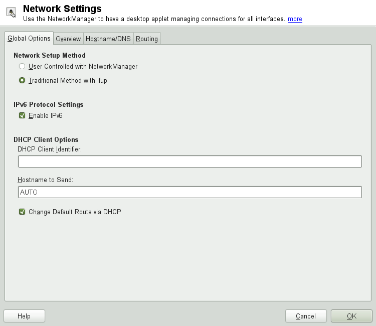
The tab of the YaST module allows you to set important global networking options, such as the use of NetworkManager, IPv6 and DHCP client options. These settings are applicable for all network interfaces.
In the choose the way network connections are managed. If you want a NetworkManager desktop applet to manage connections for all interfaces, choose . This option is well suited for switching between multiple wired and wireless networks. If you do not run a desktop environment (GNOME or KDE), or if your computer is a Xen server, virtual system, or provides network services such as DHCP or DNS in your network, use the . If NetworkManager is used, nm-applet should be used to configure network options and the , and tabs of the module are disabled. For more information on NetworkManager, see Chapter 35, Using NetworkManager.
In the choose whether you want to use the IPv6 protocol. It is possible to use IPv6 together with IPv4. By default, IPv6 is activated. However, in networks not using IPv6 protocol, response times can be faster with IPv6 protocol disabled. If you want to disable IPv6, uncheck the option. This disables autoload of the kernel module for IPv6. This will be applied after reboot.
In the configure options for the DHCP client. The must be different for each DHCP client on a single network. If left empty, it defaults to the hardware address of the network interface. However, if you are running several virtual machines using the same network interface and, therefore, the same hardware address, specify a unique free-form identifier here.
The specifies a string used for the
hostname option field when dhcpcd sends messages to DHCP server. Some
DHCP servers update name server zones (forward and reverse records)
according to this hostname (Dynamic DNS). Also, some DHCP servers
require the option field to contain
a specific string in the DHCP messages from clients. Leave
AUTO to send the current hostname (that is the one
defined in /etc/HOSTNAME). Leave the option field
empty for not sending any hostname. If yo do not want to change the
default route according to the information from DHCP,
uncheck .
23.4.1.2. Changing the Configuration of a Network Card
To change the configuration of a network card, select a card from the list of the detected cards in + in YaST and click . The dialog appears in which to adjust the card configuration using the , and tabs. For information about wireless card configuration, see Section 34.5, “Configuration with YaST”.
23.4.1.2.1. Configuring IP Addresses
You can set the IP address of the network card or the way its IP address is determined in the tab of the dialog. Both IPv4 and IPv6 addresses are supported. The network card can have (which is useful for bonding devices), a (IPv4 or IPv6) or a assigned via or or both.
If using , select whether to use (for IPv4), (for IPv6) or .
If possible, the first network card with link that is available during the installation is automatically configured to use automatic address setup via DHCP. In case of laptop computers where NetworkManager is active by default, all network cards are configured.
DHCP should also be used if you are using a DSL line but with no static IP assigned by the ISP (Internet Service Provider). If you decide to use DHCP, configure the details in in the tab of the dialog of the YaST network card configuration module. If you have a virtual host setup where different hosts communicate through the same interface, an is necessary to distinguish them.
DHCP is a good choice for client configuration but it is not ideal for server configuration. To set a static IP address, proceed as follows:
Select a card from the list of detected cards in the tab of the YaST network card configuration module and click .
In the tab, choose .
Enter the . Both IPv4 and IPv6 addresses can be used. Enter the network mask in . If the IPv6 address is used, use for prefix length in format
/64.Optionally, you can enter a fully qualified for this address, which will be written to the
/etc/hostsconfiguration file.Click .
To activate the configuration, click .
If you use the static address, the name servers and default gateway are not configured automatically. To configure name servers, proceed as described in Section 23.4.1.4, “Configuring Hostname and DNS”. To configure a gateway, proceed as described in Section 23.4.1.5, “Configuring Routing”.
23.4.1.2.2. Configuring Aliases
One network device can have multiple IP addresses, called aliases.
| Aliases Are a Compatibility Feature |
|---|---|
These so-called aliases resp. labels work with IPv4 only. With IPv6 they will be ignored. Using iproute2 network interfaces can have one or more addresses. | |
Using YaST to set an alias for your network card, proceed as follows:
Select a card from the list of detected cards in the tab of the YaST network card configuration module and click .
In the + tab, click .
Enter , , and . Do not include the interface name in the alias name.
Click .
Click .
To activate the configuration, click .
23.4.1.2.3. Changing the Device Name and Udev Rules
It is possible to change the device name of the network card when it is used. It is also possible to determine whether the network card should be identified by udev via its hardware (MAC) address or via the bus ID. The later option is preferable in large servers to ease hot swapping of cards. To set these options with YaST, proceed as follows:
Select a card from the list of detected cards in the tab of the YaST module and click .
Go to the tab. The current device name is shown in . Click .
Select whether udev should identify the card by its or . The current MAC address and bus ID of the card are shown in the dialog.
To change the device name, check the option and edit the name.
Click and .
To activate the configuration, click .
23.4.1.2.4. Changing Network Card Kernel Driver
For some network cards, several kernel drivers may be available. If the card is already configured, YaST allows you to select a kernel driver to be used from a list of available suitable drivers. It is also possible to specify options for the kernel driver. To set these options with YaST, proceed as follows:
Select a card from the list of detected cards in the tab of the YaST Network Settings module and click .
Go to the tab.
Select the kernel driver to be used in . Enter any options for the selected driver in in the form
option=value. If more options are used, they should be space-separated.Click and .
To activate the configuration, click .
23.4.1.2.5. Activating the Network Device
If you use the traditional method with ifup, you can configure your device to either start during boot, on cable connection, on card detection, manually or never. To change device start-up, proceed as follows:
In YaST select a card from the list of detected cards in + and click .
In the tab, select the desired entry from .
Choose to start the device during the system boot. With , the interface is watched for any existing physical connection. With , the interface is set as soon as available. It is similar to the option, and only differs in the fact that no error occurs if the interface is not present at boot time. Choose to control the interface manually with ifup. Choose to not start the device at all. The is similar to , but the interface does not shut down with the rcnetwork stop command. Use this if you use an nfs or iscsi root file system.
Click .
To activate the configuration, click .
Usually, only the system administrator can activate and deactivate network interfaces. If you want any user to be able to activate this interface via KInternet, select .
23.4.1.2.6. Setting Up Maximum Transfer Unit Size
You can set a maximum transmission unit (MTU) for the interface. MTU refers to the largest allowed packet size in bytes. A higher MTU brings higher bandwidth efficiency. However, large packets can block up a slow interface for some time, increasing the lag for further packets.
In YaST select a card from the list of detected cards in + and click .
In the tab, select the desired entry from the list.
Click .
To activate the configuration, click .
23.4.1.2.7. Configuring the Firewall
Without having to enter the detailed firewall setup as described in Section “Configuring the Firewall with YaST” (Chapter 14, Masquerading and Firewalls, ↑Security Guide), you can determine the basic firewall setup for your device as part of the device setup. Proceed as follows:
Open the YaST + module. In the tab, select a card from the list of detected cards and click .
Enter the tab of the dialog.
Determine the firewall zone to which your interface should be assigned. The following options are available:
- Firewall Disabled
This option is available only if the firewall is disabled and the firewall does not run at all. Only use this option if your machine is part of a greater network that is protected by an outer firewall.
- Automatically Assign Zone
This option is available only if the firewall is enabled. The firewall is running and the interface is automatically assigned to a firewall zone. The zone which contains the keyword
anyor the external zone will be used for such an interface.- Internal Zone (Unprotected)
The firewall is running, but does not enforce any rules to protect this interface. Use this option if your machine is part of a greater network that is protected by an outer firewall. It is also useful for the interfaces connected to the internal network, when the machine has more network interfaces.
- Demilitarized Zone
A demilitarized zone is an additional line of defense in front of an internal network and the (hostile) Internet. Hosts assigned to this zone can be reached from the internal network and from the Internet, but cannot access the internal network.
- External Zone
The firewall is running on this interface and fully protects it against other—presumably hostile—network traffic. This is the default option.
Click .
Activate the configuration by clicking .
23.4.1.3. Configuring an Undetected Network Card
Your card may not be detected correctly. In this case, the card is not included in the list of detected cards. If you are sure that your system includes a driver for your card, you can configure it manually. You can also configure special network device types, such as bridge, bond, TUN or TAP. To configure an undetected network card (or a special device) proceed as follows:
In the ++ dialog in YaST click .
In the dialog, set the of the interface from the available options and . If the network card is a PCMCIA or USB device, activate the respective check box and exit this dialog with . Otherwise, you can define the kernel to be used for the card and its , if necessary.
In , you can set ethtool options used by ifup for the interface. See the ethtool manual page for available options. If the option string starts with a
-(for example-K), the second word in the string is replaced with the current interface name. Otherwise (for exampleinterface_namerx onautoneg off speed 10) ifup prepends-s.interface_nameClick .
Configure any needed options, such as the IP address, device activation or firewall zone for the interface in the , , and tabs. For more information about the configuration options, see Section 23.4.1.2, “Changing the Configuration of a Network Card”.
If you selected as the device type of the interface, configure the wireless connection in the next dialog.
Click .
To activate the new network configuration, click .
23.4.1.4. Configuring Hostname and DNS
If you did not change the network configuration during installation and the wired card was already available, a hostname was automatically generated for your computer and DHCP was activated. The same applies to the name service information your host needs to integrate into a network environment. If DHCP is used for network address setup, the list of domain name servers is automatically filled with the appropriate data. If a static setup is preferred, set these values manually.
To change the name of your computer and adjust the name server search list, proceed as follows:
Go to the + tab in the module in YaST.
Enter the and, if needed, the . The domain is especially important if the machine is a mail server. Note that the hostname is global and applies to all set network interfaces.
If you are using DHCP to get an IP address, the hostname of your computer will be automatically set by the DHCP. You may want to disable this behavior if you connect to different networks, because they may assign different hostnames and changing the hostname at runtime may confuse the graphical desktop. To disable using DHCP to get an IP address uncheck .
associates your hostname with
127.0.0.2(loopback) IP address in/etc/hosts. This is an useful option if you want to have the hostname resolvable at all times, even without active network.In , select the way the DNS configuration (name servers, search list, the content of the
/etc/resolv.conffile) is modified.If the option is selected, the configuration is handled by the netconfig script which merges the data defined statically (with YaST or in the configuration files) with data obtained dynamically (from the DHCP client or NetworkManager). This default policy is sufficient in most cases.
If the option is selected, netconfig is not allowed to modify the
/etc/resolv.conffile. However, this file can be edited manually.If the option is selected, a string defining the merge policy should be specified. The string consists of a comma-separated list of interface names to be considered a valid source of settings. Except for complete interface names, basic wildcards to match multiple interfaces are allowed, as well. For example,
eth*
      ppp?
will first target all eth and then all ppp0-ppp9 interfaces. There are two special policy values that indicate how to apply the static settings defined in the/etc/sysconfig/network/configfile:STATICThe static settings have to be merged together with the dynamic settings.
STATIC_FALLBACKThe static settings are used only when no dynamic configuration is available.
For more information, see the man 8 netconfig.
Enter the and fill in the list. Name servers must be specified by IP addresses, such as 192.168.1.116, not by hostnames. Names specified in the tab are domain names used for resolving hostnames without a specified domain. If more than one is used, separate domains with commas or white space.
To activate the configuration, click .
23.4.1.5. Configuring Routing
To make your machine communicate with other machines and other networks, routing information must be given to make network traffic take the correct path. If DHCP is used, this information is automatically provided. If a static setup is used, this data must be added manually.
In YaST go to +.
Enter the IP address of the (IPv4 and IPv6 if necessary). The default gateway matches every possible destination, but if any other entry exists that matches the required address, use this instead of the default route.
More entries can be entered in the . Enter the network IP address, IP address and the . Select the through which the traffic to the defined network will be routed (the minus sign stands for any device). To omit any of these values, use the minus sign
-. To enter a default gateway into the table, usedefaultin the field.If more default routes are used, it is possible to specify the metric option to determine which route has a higher priority. To specify the metric option, enter
- metricin . The route with the highest metric is used as default. If the network device is disconnected, its route will be removed and the next one will be used. However, the current kernel does not use metric in static routing, only routing daemons like multipathd do.numberIf the system is a router, enable the option in the .
To activate the configuration, click .
23.4.2. Modem
In the YaST Control Center, access the modem configuration under +. If your modem was not automatically detected, go to the tab and open the dialog for manual configuration by clicking . Enter the interface to which the modem is connected under .
![[Tip]](admon/tip.png) | CDMA and GPRS Modems |
|---|---|
Configure supported CDMA and GPRS modems with the YaST module just as you would configure regular modems. | |
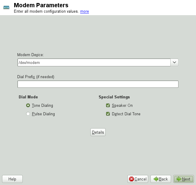
If you are behind a private branch exchange (PBX), you may need to enter a dial prefix. This is often a zero. Consult the instructions that came with the PBX to find out. Also select whether to use tone or pulse dialing, whether the speaker should be on and whether the modem should wait until it detects a dial tone. The last option should not be enabled if the modem is connected to an exchange.
Under , set the baud rate and the modem initialization strings. Only change these settings if your modem was not detected automatically or if it requires special settings for data transmission to work. This is mainly the case with ISDN terminal adapters. Leave this dialog by clicking . To delegate control over the modem to the normal user without root permissions, activate . In this way, a user without administrator permissions can activate or deactivate an interface. Under , specify a regular expression. The in KInternet, which can be modified by the normal user, must match this regular expression. If this field is left empty, the user cannot set a different without administrator permissions.
In the next dialog, select the ISP. To choose from a predefined list of ISPs operating in your country, select . Alternatively, click to open a dialog in which to provide the data for your ISP. This includes a name for the dial-up connection and ISP as well as the login and password provided by your ISP. Enable to be prompted for the password each time you connect.
In the last dialog, specify additional connection options:
If you enable , set at least one name server. Use this feature only if your Internet connection is inexpensive, because there are programs that periodically request data from the Internet.
This option is enabled by default, with the effect that the name server address is updated each time you connect to the Internet.
If the provider does not transmit its domain name server after connecting, disable this option and enter the DNS data manually.
If this options is enabled, the connection is automatically reestablished after failure.
This option disables the detection of any prompts from the dial-up server. If the connection build-up is slow or does not work at all, try this option.
Selecting this option activates the firewall and sets the interface as external. This way, you are protected from outside attacks for the duration of your Internet connection.
With this option, specify a period of network inactivity after which the modem disconnects automatically.
This opens the address configuration dialog. If your ISP does not assign a dynamic IP address to your host, disable then enter your host's local IP address and the remote IP address. Ask your ISP for this information. Leave enabled and close the dialog by selecting .
Selecting returns to the original dialog, which displays a summary of the modem configuration. Close this dialog with .
23.4.3. ISDN
Use this module to configure one or several ISDN cards for your system. If YaST did not detect your ISDN card, click on in the tab and manually select your card. Multiple interfaces are possible, but several ISPs can be configured for one interface. In the subsequent dialogs, set the ISDN options necessary for the proper functioning of the card.
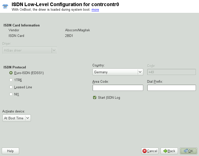
In the next dialog, shown in Figure 23.5, “ISDN Configuration”, select the protocol to use. The default is , but for older or larger exchanges, select . If you are in the US, select . Select your country in the relevant field. The corresponding country code then appears in the field next to it. Finally, provide your and the if necessary. If you do not want to log all your ISDN traffic, uncheck the option.
defines how the ISDN interface should
be started: causes the ISDN driver to be
initialized each time the system boots.
requires you to load the ISDN driver as root with the command
rcisdn start. , used for
PCMCIA or USB devices, loads the driver after the device is plugged in.
When finished with these settings, select .
In the next dialog, specify the interface type for your ISDN card and add
ISPs to an existing interface. Interfaces may be either the
SyncPPP or the RawIP
type, but most ISPs operate in the SyncPPP mode,
which is described below.
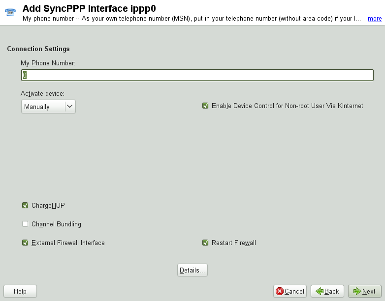
The number to enter for depends on your particular setup:
- ISDN Card Directly Connected to Phone Outlet
A standard ISDN line provides three phone numbers (called multiple subscriber numbers, or MSNs). If the subscriber asked for more, there may be up to 10. One of these MSNs must be entered here, but without your area code. If you enter the wrong number, your phone operator automatically falls back to the first MSN assigned to your ISDN line.
- ISDN Card Connected to a Private Branch Exchange
Again, the configuration may vary depending on the equipment installed:
Smaller private branch exchanges (PBX) built for home purposes mostly use the Euro-ISDN (EDSS1) protocol for internal calls. These exchanges have an internal S0 bus and use internal numbers for the equipment connected to them.
Use one of the internal numbers as your MSN. You should be able to use at least one of the exchange's MSNs that have been enabled for direct outward dialing. If this does not work, try a single zero. For further information, consult the documentation delivered with your phone exchange.
Larger phone exchanges designed for businesses normally use the 1TR6 protocol for internal calls. Their MSN is called EAZ and usually corresponds to the direct-dial number. For the configuration under Linux, it should be sufficient to enter the last digit of the EAZ. As a last resort, try each of the digits from 1 to 9.
For the connection to be terminated just before the next charge unit is due, enable . However, remember that may not work with every ISP. You can also enable channel bundling (multilink PPP) by selecting the corresponding option. Finally, you can enable the firewall for your link by selecting and . To enable the normal user without administrator permissions to activate or deactivate the interface, select the .
opens a dialog in which to implement more complex connection schemes which are not relevant for normal home users. Leave the dialog by selecting .
In the next dialog, configure IP address settings. If you have not been given a static IP by your provider, select . Otherwise, use the fields provided to enter your host's local IP address and the remote IP address according to the specifications of your ISP. If the interface should be the default route to the Internet, select . Each host can only have one interface configured as the default route. Leave this dialog by selecting .
The following dialog allows you to set your country and select an ISP. The ISPs included in the list are call-by-call providers only. If your ISP is not in the list, select . This opens the dialog in which to enter all the details for your ISP. When entering the phone number, do not include any blanks or commas among the digits. Finally, enter your login and the password as provided by the ISP. When finished, select .
To use on a stand-alone workstation,
specify the name server (DNS server) as well. Most ISPs support dynamic
DNS, which means the IP address of a name server is sent by the ISP each
time you connect. For a single workstation, however, you still need to
provide a placeholder address like
192.168.22.99. If your ISP
does not support dynamic DNS, specify the name server IP addresses of the
ISP. If desired, specify a time-out for the connection—the period
of network inactivity (in seconds) after which the connection should be
automatically terminated. Confirm your settings with
. YaST displays a summary of the configured
interfaces. To activate these settings, select .
23.4.4. Cable Modem
In some countries it is quite common to access the Internet through the TV cable network. The TV cable subscriber usually gets a modem that is connected to the TV cable outlet on one side and to a computer network card on the other (using a 10Base-TG twisted pair cable). The cable modem then provides a dedicated Internet connection with a fixed IP address.
Depending on the instructions provided by your ISP, when configuring the network card either select or . Most providers today use DHCP. A static IP address often comes as part of a special business account.
23.4.5. DSL
To configure your DSL device, select the module from the YaST section. This YaST module consists of several dialogs in which to set the parameters of DSL links based on one of the following protocols:
PPP over Ethernet (PPPoE)
PPP over ATM (PPPoATM)
CAPI for ADSL (Fritz Cards)
Point-to-Point Tunneling Protocol (PPTP)—Austria
In the tab of the dialog, you will find a list of installed DSL devices. To change the configuration of a DSL device, select it in the list and click . If you click , you can manually configure a new DSL device.
The configuration of a DSL connection based on PPPoE or PPTP requires
that the corresponding network card be set up in the correct way. If you
have not done so yet, first configure the card by selecting
(see
Section 23.4.1, “Configuring the Network Card with YaST”). In the case of a DSL
link, addresses may be assigned automatically but not via DHCP, which is
why you should not enable the option .
Instead, enter a static dummy address for the interface, such as
192.168.22.1. In
, enter
255.255.255.0. If you are
configuring a stand-alone workstation, leave empty.
| |
Values in and are only placeholders. They are only needed to initialize the network card and do not represent the DSL link as such. | |
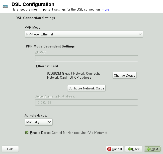
In the first DSL configuration dialog (see
Figure 23.7, “DSL Configuration”), select the and the to which the DSL
modem is connected (in most cases, this is
eth0). Then use
to specify whether the DSL link should
be established during the boot process. Click to authorize the normal
user without root permissions to activate or deactivate the interface
with KInternet.
In the next dialog select your country and choose from a number of ISPs operating in it. The details of any subsequent dialogs of the DSL configuration depend on the options set so far, which is why they are only briefly mentioned in the following paragraphs. For details on the available options, read the detailed help available from the dialogs.
To use on a stand-alone workstation,
also specify the name server (DNS server). Most ISPs support dynamic
DNS—the IP address of a name server is sent by the ISP each time
you connect. For a single workstation, however, provide a placeholder
address like 192.168.22.99. If
your ISP does not support dynamic DNS, enter the name server IP address
provided by your ISP.
defines a period of network inactivity after which to terminate the connection automatically. A reasonable time-out value is between 60 and 300 seconds. If is disabled, it may be useful to set the time-out to zero to prevent automatic hang-up.
The configuration of T-DSL is very similar to the DSL setup. Just select as your provider and YaST opens the T-DSL configuration dialog. In this dialog, provide some additional information required for T-DSL—the line ID, the T-Online number, the user code and your password. All of these should be included in the information you received after subscribing to T-DSL.
23.5. NetworkManager
NetworkManager is the ideal solution for laptops and other portable computers. With NetworkManager, you do not need to worry about configuring network interfaces and switching between networks when you are moving.
23.5.1. NetworkManager and ifup
However, NetworkManager is not a suitable solution for all cases, so you can still choose between the traditional method for managing network connections (ifup) and NetworkManager. If you want to manage your network connection with NetworkManager, enable NetworkManager in the YaST Network Settings module as described in Section 35.2, “Enabling NetworkManager” and configure your network connections with NetworkManager. For a list of use cases and a detailed description how to configure and use NetworkManager, refer to Chapter 35, Using NetworkManager.
Some differences between ifup and NetworkManager include:
rootPrivilegesIf you use NetworkManager for network setup, you can easily switch, stop or start your network connection at any time from within your desktop environment using an applet. NetworkManager also makes it possible to change and configure wireless card connections without requiring
rootprivileges. For this reason, NetworkManager is the ideal solution for a mobile workstation.Traditional configuration with ifup also provides some ways to switch, stop or start the connection with or without user intervention, like user-managed devices. However, this always requires
rootprivileges to change or configure a network device. This is often a problem for mobile computing, where it is not possible to preconfigure all the connection possibilities.- Types of Network Connections
Both traditional configuration and NetworkManager can handle network connections with a wireless network (with WEP, WPA-PSK, and WPA-Enterprise access), dial-up and wired networks using DHCP and static configuration. They also support connection through VPN.
NetworkManager tries to keep your computer connected at all times using the best connection available. If the network cable is accidentally disconnected, it tries to reconnect. It can find the network with the best signal strength from the list of your wireless connections and automatically use it to connect. To get the same functionality with ifup, a great deal of configuration effort is required.
23.5.2. NetworkManager Functionality and Configuration Files
The individual network connection settings created with NetworkManager are stored
in configuration profiles. The system connections
configured with either NetworkManager or YaST can be found in
/etc/sysconfig/network/ifcfg-*. Any user-defined
connections are stored in GConf for GNOME.
In case no profile is configured, NetworkManager automatically creates one and
names it Auto $INTERFACE-NAME. That is made in an
attempt to work without any configuration for as many cases as (securely)
possible. If the automatically created profiles do not suit your needs,
use the network connection configuration dialogs provided by KDE or GNOME
to modify them as desired. For more information, refer to
Section 35.3, “Configuring Network Connections”.
23.5.3. Controlling and Locking Down NetworkManager Features
On centrally administered machines, certain NetworkManager features can be controlled or disabled with PolicyKit, for example if a user is allowed to modify administrator defined connections or if a user is allowed to define his own network configurations. To view or change the respective NetworkManager policies, start the graphical tool for PolicyKit. In the tree on the left side, find them below the entry. For an introduction to PolicyKit and details on how to use it, refer to Chapter 9, PolicyKit (↑Security Guide).
The following table gives an overview of the PolicyKit identifiers related to NetworkManager:
Table 23.5. PolicyKit Identifiers for NetworkManager
|
Identifier |
Description |
|---|---|
|
org.freedesktop.NetworkManager.enable-disable-network |
Enable or disable system networking |
|
org.freedesktop.NetworkManager.sleep-wake |
Put NetworkManager to sleep or wake it up |
|
org.freedesktop.NetworkManager.enable-disable-wwan |
Enable or disable mobile broadband devices |
|
org.freedesktop.NetworkManager.network-control |
Allow control of network connections |
|
org.freedesktop.NetworkManager.enable-disable-wifi |
Enable or disable WiFi devices |
|
org.freedesktop.NetworkManager.use-user-connections |
Allow use of user-specific connections |
|
org.freedesktop.network-manager-settings.system.modify |
Modify system connections |
|
org.freedesktop.network-manager-settings.system.wifi.share.open |
Connection sharing via an open WiFi network |
|
org.freedesktop.network-manager-settings.system.wifi.share.protected |
Connection sharing via a protected WiFi network |
23.6. Configuring a Network Connection Manually
Manual configuration of the network software should always be the last alternative. Using YaST is recommended. However, this background information about the network configuration can also assist your work with YaST.
When the Kernel detects a network card and creates a corresponding network interface, it assigns the device a name depending on the order of device discovery, or order of the loading of the Kernel modules. The default Kernel device names are only predictable in very simple or tightly controlled hardware environments. Systems which allow adding or removing hardware during runtime or support automatic configuration of devices cannot expect stable network device names assigned by the Kernel across reboots.
However, all system configuration tools rely on persistent interface
names. This problem is solved by udev. The udev persistent net generator
(/lib/udev/rules.d/75-persistent-net-generator.rules)
generates a rule matching the hardware (using its hardware address by
default) and assigns a persistently unique interface for the hardware. The
udev database of network interfaces is stored in the file
/etc/udev/rules.d/70-persistent-net.rules. Every line
in the file describes one network interface and specifies its persistent
name. System administrators can change the assigned names by editing the
NAME="" entries. The persistent rules can also be
modified using YaST.
Table 23.6, “Manual Network Configuration Scripts” summarizes the most important scripts involved in the network configuration.
Table 23.6. Manual Network Configuration Scripts
|
Command |
Function |
|---|---|
|
ifup, ifdown, ifstatus |
The |
|
rcnetwork |
The |
For more information about udev and persistent device names, see
Chapter 20, Dynamic Kernel Device Management with udev.
23.6.1. Configuration Files
This section provides an overview of the network configuration files and explains their purpose and the format used.
23.6.1.1. /etc/sysconfig/network/ifcfg-*
These files contain the configurations for network interfaces. They
include information such as the start mode and the IP address. Possible
parameters are described in the manual page of
ifup. Additionally, most variables from the
dhcp and wireless files can be
used in the ifcfg-* files if a general setting
should be used for only one interface. However, most of the
/etc/sysconfig/network/config variables are global
and cannot be overridden in ifcfg-files. For example
NETWORKMANAGER or
NETCONFIG_* variables are global.
For ifcfg.template, see
Section 23.6.1.2, “/etc/sysconfig/network/config, /etc/sysconfig/network/dhcp, and /etc/sysconfig/network/wireless”.
23.6.1.2. /etc/sysconfig/network/config, /etc/sysconfig/network/dhcp, and /etc/sysconfig/network/wireless
The file config contains general settings for the
behavior of ifup, ifdown and
ifstatus. dhcp contains settings
for DHCP and wireless for wireless LAN cards. The
variables in all three configuration files are commented. Some of the
variables from /etc/sysconfig/network/config can
also be used in ifcfg-* files, where they are given
a higher priority. The
/etc/sysconfig/network/ifcfg.template file lists
variables that can be specified in a per interface scope. However, most
of the /etc/sysconfig/network/config variables are
global and cannot be overridden in ifcfg-files. For example,
NETWORKMANAGER or
NETCONFIG_* variables are global.
23.6.1.3. /etc/sysconfig/network/routes and /etc/sysconfig/network/ifroute-*
The static routing of TCP/IP packets is determined here. All the static
routes required by the various system tasks can be entered in the
/etc/sysconfig/network/routes file: routes to a
host, routes to a host via a gateway and routes to a network. For each
interface that needs individual routing, define an additional
configuration file:
/etc/sysconfig/network/ifroute-*. Replace
* with the name of the interface. The entries in the
routing configuration files look like this:
# Destination     Dummy/Gateway     Netmask            Device
#
127.0.0.0         0.0.0.0           255.255.255.0      lo
204.127.235.0     0.0.0.0           255.255.255.0      eth0
default           204.127.235.41    0.0.0.0            eth0
207.68.156.51     207.68.145.45     255.255.255.255    eth1
192.168.0.0       207.68.156.51     255.255.0.0        eth1
The route's destination is in the first column. This column may contain the IP address of a network or host or, in the case of reachable name servers, the fully qualified network or hostname.
The second column contains the default gateway or a gateway through
which a host or network can be accessed. The third column contains the
netmask for networks or hosts behind a gateway. For example, the mask is
255.255.255.255 for a host
behind a gateway.
The fourth column is only relevant for networks connected to the local host such as loopback, Ethernet, ISDN, PPP and dummy device. The device name must be entered here.
An (optional) fifth column can be used to specify the type of a route.
Columns that are not needed should contain a minus sign
- to ensure that the parser correctly interprets the
command. For details, refer to the routes(5)
man page.
The unified format for IPv4 and IPv6 now looks as follows:
prefix/lengthgateway- [interface]
And the so-called compatibility format looks accordingly:
prefixgatewaylength[interface]
For IPv4 you still can use the old format with netmask:
ipv4-networkgatewayipv4-netmask[interface]
The following examples are equivalent:
2001:db8:abba:cafe::/64 2001:db8:abba:cafe::dead  -            eth0
208.77.188.0/24         208.77.188.166            -            eth0

2001:db8:abba:cafe::    2001:db8:abba:cafe::dead 64            eth0
208.77.188.0            208.77.188.166           24            eth0

208.77.188.0            208.77.188.166           255.255.255.0 eth0
23.6.1.4. /etc/resolv.conf
The domain to which the host belongs is specified in this file (keyword
search). Also listed is the status of the name
server address to access (keyword nameserver).
Multiple domain names can be specified in the file. When resolving a
name that is not fully qualified, an attempt is made to generate one by
attaching the individual search entries.
Multiple name servers can be specified in multiple lines, each beginning
with nameserver. Comments are preceded by
# signs. Example 23.5, “/etc/resolv.conf”
shows what /etc/resolv.conf could look like.
However, the /etc/resolv.conf should not be edited
by hand. Instead, it is generated by the netconfig
script. To define static DNS configuration without using YaST, edit
the appropriate variables manually in the
/etc/sysconfig/network/config file:
NETCONFIG_DNS_STATIC_SEARCHLISTlist of DNS domain names used for hostname lookup
NETCONFIG_DNS_STATIC_SERVERSlist of name server IP addresses to use for hostname lookup
NETCONFIG_DNS_FORWARDERdefines the name of the DNS forwarder that has to be configured
To disable DNS configuration using netconfig, set
NETCONFIG_DNS_POLICY=''. For more information about
netconfig, see man 8 netconfig.
Example 23.5. /etc/resolv.conf
# Our domain
search example.com
#
# We use dns.example.com (192.168.1.116) as nameserver
nameserver 192.168.1.116
23.6.1.5. /sbin/netconfig
netconfig is a modular tool to manage additional network configuration settings. It merges statically defined settings with settings provided by autoconfiguration mechanisms as DHCP or PPP according to a predefined policy. The required changes are applied to the system by calling the netconfig modules that are responsible for modifying a configuration file and restarting a service or a similar action.
netconfig recognizes three main actions. The netconfig modify and netconfig remove commands are used by daemons such as DHCP or PPP to provide or remove settings to netconfig. Only the netconfig update command is available for the user:
- modify
The netconfig modify command modifies the current interface and service specific dynamic settings and updates the network configuration. Netconfig reads settings from standard input or from a file specified with the
--lease-fileoption and internally stores them until a system reboot (or the next modify or remove action). Already existing settings for the same interface and service combination are overwritten. The interface is specified by thefilename-iparameter. The service is specified by theinterface_name-sparameter.service_name- remove
The netconfig remove command removes the dynamic settings provided by a modificatory action for the specified interface and service combination and updates the network configuration. The interface is specified by the
-iparameter. The service is specified by theinterface_name-sparameter.service_name- update
The netconfig update command updates the network configuration using current settings. This is useful when the policy or the static configuration has changed. Use the
-mparameter, if you want to update a specified service only (module_typedns,nis, orntp).
The netconfig policy and the static configuration settings are defined
either manually or using YaST in the
/etc/sysconfig/network/config file. The dynamic
configuration settings provided by autoconfiguration tools as DHCP or
PPP are delivered directly by these tools with the netconfig
modify and netconfig remove actions. NetworkManager
also uses netconfig modify and netconfig
remove actions. When NetworkManager is enabled, netconfig (in policy
mode auto) uses only NetworkManager settings, ignoring settings
from any other interfaces configured using the traditional ifup method.
If NetworkManager does not provide any setting, static settings are used as a
fallback. A mixed usage of NetworkManager and the traditional ifup method is not
supported.
For more information about netconfig, see man 8 netconfig.
23.6.1.6. /etc/hosts
In this file, shown in Example 23.6, “/etc/hosts”, IP
addresses are assigned to hostnames. If no name server is implemented,
all hosts to which an IP connection will be set up must be listed here.
For each host, enter a line consisting of the IP address, the fully
qualified hostname, and the hostname into the file. The IP address must
be at the beginning of the line and the entries separated by blanks and
tabs. Comments are always preceded by the # sign.
Example 23.6. /etc/hosts
127.0.0.1 localhost
192.168.2.100 jupiter.example.com jupiter
192.168.2.101 venus.example.com venus
23.6.1.7. /etc/networks
Here, network names are converted to network addresses. The format is
similar to that of the hosts file, except the
network names precede the addresses. See
Example 23.7, “/etc/networks”.
23.6.1.8. /etc/host.conf
Name resolution—the translation of host and network names via the
resolver library—is controlled by this file.
This file is only used for programs linked to libc4 or libc5. For
current glibc programs, refer to the settings in
/etc/nsswitch.conf. A parameter must always stand
alone in its own line. Comments are preceded by a #
sign. Table 23.7, “Parameters for /etc/host.conf” shows the parameters
available. A sample /etc/host.conf is shown in
Example 23.8, “/etc/host.conf”.
Table 23.7. Parameters for /etc/host.conf
|
order hosts, bind |
Specifies in which order the services are accessed for the name resolution. Available arguments are (separated by blank spaces or commas): |
|
hosts: searches the
| |
|
bind: accesses a name server | |
|
nis: uses NIS | |
|
multi on/off |
Defines if a host entered in |
|
nospoof on spoofalert on/off |
These parameters influence the name server spoofing but do not exert any influence on the network configuration. |
|
trim domainname |
The specified domain name is separated from the hostname after
hostname resolution (as long as the hostname includes the domain
name). This option is useful only if names from the local domain
are in the |
Example 23.8. /etc/host.conf
# We have named running
order hosts bind
# Allow multiple address
multi on
23.6.1.9. /etc/nsswitch.conf
The introduction of the GNU C Library 2.0 was accompanied by the
introduction of the Name Service Switch (NSS).
Refer to the nsswitch.conf(5) man page and
The GNU C Library Reference Manual for details.
The order for queries is defined in the file
/etc/nsswitch.conf. A sample
nsswitch.conf is shown in
Example 23.9, “/etc/nsswitch.conf”. Comments are preceded by
# signs. In this example, the entry under the
hosts database means that a request is sent to
/etc/hosts (files) via
DNS.
Example 23.9. /etc/nsswitch.conf
passwd:     compat
group:      compat

hosts:      files dns
networks:   files dns

services:   db files
protocols:  db files
rpc:        files
ethers:     files
netmasks:   files
netgroup:   files nis
publickey:  files

bootparams: files
automount:  files nis
aliases:    files nis
shadow:     compat
The “databases” available over NSS are listed in Table 23.8, “Databases Available via /etc/nsswitch.conf”. The configuration options for NSS databases are listed in Table 23.9, “Configuration Options for NSS “Databases””.
Table 23.8. Databases Available via /etc/nsswitch.conf
|
|
Mail aliases implemented by |
|
|
Ethernet addresses. |
|
|
List of network and their subnet masks. Only needed, if you use subnetting. |
|
|
For user groups used by |
|
|
For hostnames and IP addresses, used by
|
|
|
Valid host and user lists in the network for the purpose of
controlling access permissions; see the
|
|
|
Network names and addresses, used by
|
|
|
Public and secret keys for Secure_RPC used by NFS and NIS+.. |
|
|
User passwords, used by |
|
|
Network protocols, used by |
|
|
Remote procedure call names and addresses, used by
|
|
|
Network services, used by |
|
|
Shadow passwords of users, used by |
Table 23.9. Configuration Options for NSS “Databases”
|
|
directly access files, for example,
|
|
|
access via a database |
|
|
NIS, see also Chapter 3, Using NIS (↑Security Guide) |
|
|
can only be used as an extension for |
|
|
can only be used as an extension for |
23.6.1.10. /etc/nscd.conf
This file is used to configure nscd (name service cache daemon). See the
nscd(8) and
nscd.conf(5) man pages. By default, the system
entries of passwd and groups are
cached by nscd. This is important for the performance of directory
services, like NIS and LDAP, because otherwise the network connection
needs to be used for every access to names or groups.
hosts is not cached by default, because the mechanism
in nscd to cache hosts makes the local system unable to trust forward
and reverse lookup checks. Instead of asking nscd to cache names, set up
a caching DNS server.
If the caching for passwd is activated, it usually
takes about fifteen seconds until a newly added local user is
recognized. Reduce this waiting time by restarting nscd with the command
rcnscd restart.
23.6.1.11. /etc/HOSTNAME 
This contains the fully qualified hostname with the domain name attached. This file is read by several scripts while the machine is booting. It must contain only one line (in which the hostname is set).
23.6.2. Testing the Configuration
Before you write your configuration to the configuration files, you can test it. To set up a test configuration, use the ip command. To test the connection, use the ping command. Older configuration tools, ifconfig and route, are also available.
The commands ip, ifconfig and route change the network configuration directly without saving it in the configuration file. Unless you enter your configuration in the correct configuration files, the changed network configuration is lost on reboot.
23.6.2.1. Configuring a Network Interface with ip
ip is a tool to show and configure network devices, routing, policy routing, and tunnels.
ip is a very complex tool. Its common syntax is
ip options
object
command
- link
This object represents a network device.
- address
This object represents the IP address of device.
- neighbor
This object represents a ARP or NDISC cache entry.
- route
This object represents the routing table entry.
- rule
This object represents a rule in the routing policy database.
- maddress
This object represents a multicast address.
- mroute
This object represents a multicast routing cache entry.
- tunnel
This object represents a tunnel over IP.
If no command is given, the default command is used (usually list).
Change the state of a device with the command ip link
set device_namecommand.
For example, to deactivate device eth0, enter ip link
set eth0 down. To activate it again, use
ip link set eth0 up.
After activating a device, you can configure it. To set the IP address,
use ip addr
add ip_address + dev
device_namebrd), enter ip
addr add 192.168.12.154/30 brd + dev
eth0.
To have a working connection, you must also configure the default
gateway. To set a gateway for your system, enter ip route
add gateway_ip_address. To translate one
IP address to another, use nat: ip route add
nat ip_address via other_ip_address.
To display all devices, use ip link ls. To display
the running interfaces only, use ip link ls up. To
print interface statistics for a device, enter ip -s link
ls device_name. To view addresses of
your devices, enter ip addr. In the output of the
ip addr, also find information about MAC addresses of
your devices. To show all routes, use ip route show.
For more information about using ip, enter
ip help or see the
ip(8) man page. The help
option is also available for all ip subcommands. If, for example, you need
help for ip addr, enter
ip addr help. Find the ip
manual in
/usr/share/doc/packages/iproute2/ip-cref.pdf.
23.6.2.2. Testing a Connection with ping
The ping command is the standard tool for testing whether a TCP/IP connection works. It uses the ICMP protocol to send a small data packet, ECHO_REQUEST datagram, to the destination host, requesting an immediate reply. If this works, ping displays a message to that effect, which indicates that the network link is basically functioning.
ping does more than only test the function of the connection between two computers: it also provides some basic information about the quality of the connection. In Example 23.10, “Output of the Command ping”, you can see an example of the ping output. The second-to-last line contains information about the number of transmitted packets, packet loss, and total time of ping running.
As the destination, you can use a hostname or IP address, for example,
ping example.com or
ping 192.168.3.100. The program sends
packets until you press
Ctrl+C.
If you only need to check the functionality of the connection, you can
limit the number of the packets with the -c option. For
example to limit ping to three packets, enter
ping -c 3 example.com.
Example 23.10. Output of the Command ping
ping -c 3 example.com
PING example.com (192.168.3.100) 56(84) bytes of data.
64 bytes from example.com (192.168.3.100): icmp_seq=1 ttl=49 time=188 ms
64 bytes from example.com (192.168.3.100): icmp_seq=2 ttl=49 time=184 ms
64 bytes from example.com (192.168.3.100): icmp_seq=3 ttl=49 time=183 ms
--- example.com ping statistics ---
3 packets transmitted, 3 received, 0% packet loss, time 2007ms
rtt min/avg/max/mdev = 183.417/185.447/188.259/2.052 ms
The default interval between two packets is one second. To change the
interval, ping provides the option -i. For example, to
increase the ping interval to ten seconds, enter
ping -i 10 example.com.
In a system with multiple network devices, it is sometimes useful to
send the ping through a specific interface address. To do so, use the
-I option with the name of the selected device, for
example, ping -I wlan1
example.com.
For more options and information about using ping, enter
ping -h or see the
ping (8) man page.
| Pinging IPv6 Addresses |
|---|---|
For IPv6 addresses use the ping6 command. Note, to
ping link-local addresses, you must specify the interface with
ping6 -I eth1 fe80::117:21ff:feda:a425 | |
23.6.2.3. Configuring the Network with ifconfig
ifconfig is a network configuration tool.
| ifconfig and ip |
|---|---|
The ifconfig tool is obsolete. Use ip instead. In contrast to ip, you can use ifconfig only for interface configuration. It limits interface names to 9 characters. | |
Without arguments, ifconfig displays the status of the currently active
interfaces. As you can see in
Example 23.11, “Output of the ifconfig Command”, ifconfig has very
well-arranged and detailed output. The output also contains information
about the MAC address of your device (the value of
HWaddr) in the first line.
Example 23.11. Output of the ifconfig Command
eth0      Link encap:Ethernet  HWaddr 00:08:74:98:ED:51
          inet6 addr: fe80::208:74ff:fe98:ed51/64 Scope:Link
          UP BROADCAST MULTICAST  MTU:1500  Metric:1
          RX packets:634735 errors:0 dropped:0 overruns:4 frame:0
          TX packets:154779 errors:0 dropped:0 overruns:0 carrier:1
          collisions:0 txqueuelen:1000
          RX bytes:162531992 (155.0 Mb)  TX bytes:49575995 (47.2 Mb)
          Interrupt:11 Base address:0xec80

lo        Link encap:Local Loopback
          inet addr:127.0.0.1  Mask:255.0.0.0
          inet6 addr: ::1/128 Scope:Host
          UP LOOPBACK RUNNING  MTU:16436  Metric:1
          RX packets:8559 errors:0 dropped:0 overruns:0 frame:0
          TX packets:8559 errors:0 dropped:0 overruns:0 carrier:0
          collisions:0 txqueuelen:0
          RX bytes:533234 (520.7 Kb)  TX bytes:533234 (520.7 Kb)

wlan1     Link encap:Ethernet  HWaddr 00:0E:2E:52:3B:1D
          inet addr:192.168.2.4  Bcast:192.168.2.255  Mask:255.255.255.0
          inet6 addr: fe80::20e:2eff:fe52:3b1d/64 Scope:Link
          UP BROADCAST NOTRAILERS RUNNING MULTICAST  MTU:1500  Metric:1
          RX packets:50828 errors:0 dropped:0 overruns:0 frame:0
          TX packets:43770 errors:0 dropped:0 overruns:0 carrier:0
          collisions:0 txqueuelen:1000
          RX bytes:45978185 (43.8 Mb)  TX bytes:7526693 (7.1 MB)
For more options and information about using ifconfig, enter
ifconfig -h or see the
ifconfig (8) man page.
23.6.2.4. Configuring Routing with route
route is a program for manipulating the IP routing table. You can use it to view your routing configuration and to add or remove routes.
| route and ip |
|---|---|
The program route is obsolete. Use ip instead. | |
route is especially useful if you need quick and comprehensible
information about your routing configuration to determine problems with
routing. To view your current routing configuration, enter
route -n as root.
Example 23.12. Output of the route -n Command
route -n
Kernel IP routing table
Destination     Gateway         Genmask         Flags   MSS Window  irtt Iface
10.20.0.0       *               255.255.248.0   U         0 0          0 eth0
link-local      *               255.255.0.0     U         0 0          0 eth0
loopback        *               255.0.0.0       U         0 0          0 lo
default         styx.exam.com   0.0.0.0         UG        0 0          0 eth0
For more options and information about using route, enter
route -h or see the
route (8) man page.
23.6.3. Start-Up Scripts
Apart from the configuration files described above, there are also various scripts that load the network programs while the machine is booting. These are started as soon as the system is switched to one of the multiuser runlevels. Some of these scripts are described in Table 23.10, “Some Start-Up Scripts for Network Programs”.
Table 23.10. Some Start-Up Scripts for Network Programs
|
This script handles the configuration of the network interfaces. If the network service was not started, no network interfaces are implemented. | |
|
Starts xinetd. xinetd can be used to make server services available on the system. For example, it can start vsftpd whenever an FTP connection is initiated. | |
|
Starts the rpcbind utility that converts RPC program numbers to universal addresses. It is needed for RPC services, such as an NFS server. | |
|
Starts the NFS server. | |
|
Controls the postfix process. | |
|
Starts the NIS server. | |
|
Starts the NIS client. |
23.7. smpppd as Dial-up Assistant
Some home users do not have a dedicated line connecting them to the Internet. Instead, they use dial-up connections. Depending on the dial-up method (ISDN or DSL), the connection is controlled by ipppd or pppd. Basically, all that needs to be done to go online is to start these programs correctly.
If you have a flat-rate connection that does not generate any additional costs for the dial-up connection, simply start the respective daemon. Control the dial-up connection with a desktop applet or a command-line interface. If the Internet gateway is not the host you are using, you might want to control the dial-up connection by way of a network host.
This is where smpppd (SUSE Meta PPP Daemon) is involved. It provides a uniform interface for auxiliary programs and acts in two directions. First, it programs the required pppd or ipppd and controls its dial-up properties. Second, it makes various providers available to the user programs and transmits information about the current status of the connection. As smpppd can also be controlled by way of the network, it is suitable for controlling dial-up connections to the Internet from a workstation in a private subnetwork.
23.7.1. Configuring smpppd
The connections provided by smpppd are automatically configured by YaST. The actual dial-up programs KInternet and cinternet are also preconfigured. Manual settings are only required to configure additional features of smpppd such as remote control.
The configuration file of smpppd is
/etc/smpppd.conf. By default, it does not enable
remote control. The most important options of this configuration file
are:
- open-inet-socket =
yes|no To control smpppd via the network, set this option to
yes. smpppd listens on port3185. If this parameter is set toyes, the parametersbind-address,host-rangeandpasswordmust be set accordingly.- bind-address =
ip address If a host has several IP addresses, use this parameter to determine at which IP address smpppd should accept connections. The default is to listen at all addresses.
- host-range =
min ipmax ip The parameter
host-rangedefines a network range. Hosts whose IP addresses are within this range are granted access to smpppd. All hosts not within this range are denied access.- password =
password By assigning a password, limit the clients to authorized hosts. As this is a plain-text password, you should not overrate the security it provides. If no password is assigned, all clients are permitted to access smpppd.
- slp-register =
yes|no With this parameter, the smpppd service can be announced in the network via SLP.
More information about smpppd is available in the
smpppd(8) and
smpppd.conf(5) man pages.
23.7.2. Configuring qinternet for Remote Use
qinternet can be used to control a local or remote smpppd.
cinternet is the command-line counterpart to the graphical KInternet. To
prepare these utilities for use with a remote smpppd, edit the
configuration file /etc/smpppd-c.conf manually or
using qinternet. This file only uses four options:
- sites =
list of sites list of siteswhere the front-ends search for smpppd. The front-ends test the options in the order specified here.localorders the establishment of a connection to the local smpppd.gatewaypoints to an smpppd on the gateway.config-fileindicates that the connection should be established to the smpppd specified in theserverandportoptions in/etc/smpppd-c.conf.slporders the front-ends to connect to an smpppd found via SLP.- server =
server The host on which smpppd runs.
- port =
port The port on which smpppd runs.
- password =
password The password selected for smpppd.